MODUL 3
PERCOBAAN 2 KONDISI 2
1. Rangkai semua komponen sesuai kondisi yang dipilih
2. Buat program di aplikasi arduino IDE
3. Setelah selesai masukkan program ke arduino di proteus
4. Jalankan program pada simulasi dan cobakan sesuai dengan modul dan kondisi
5. Selesai
2. Hardware dan diagram blok
[Kembali]
a. hardware

1. Arduino Uno
2. Dipswitch
3. 7-Segment common cathode
2. Dipswitch
3. 7-Segment common cathode
b. Digram Blok

3. Rangkaian Simulasi dan Prinsip kerja
[Kembali]
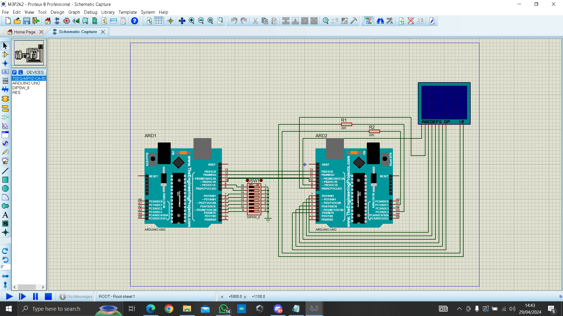
Rangkaian sebelum disimulasi

Rangkaian setelah disimulasi
PRINSIP KERJA
Pada rangkaian tersebut, dipswitch berperan sebagai input yang dihubungkan ke kaki analog arduino. outputnya yaitu 7-segment common cathode.
Rangkaian dapat disimulasikan setelah kodingan arduino dari arduino IDE dimasukkan ke arduino pada proteus. Dimana kodingan arduino diatur untuk setiap 1 Switch aktif muncul angka berbeda pada digit ke 1, Setiap Switch aktif muncul angka pada kedua digit.
4. FlowChart
[Kembali]
a. Listing Program
Master
#include <SPI.h>
int dip[] = {2, 3, 4, 5, 6, 7, 8, 9};
int dipvalue[] = {};
int dipCount = 0; // Variable to count active dip switches
void setup() {
Serial.begin(9600);
for (int i = 0; i < 8; i++) {
pinMode(dip[i], INPUT_PULLUP);
}
SPI.begin();
SPI.setClockDivider(SPI_CLOCK_DIV8);
digitalWrite(SS, HIGH);
}
void loop() {
byte Mastersend = 0;
for (int i = 0; i < 8; i++) {
dipvalue[i] = digitalRead(dip[i]);
if (dipvalue[i] == LOW) {
dipCount++; // Increment dip switch count if active
}
}
if (dipCount == 1) {
Mastersend = 1; // Set Mastersend to 1 if only one dip switch is active
} else if (dipCount == 2) {
Mastersend = 2; // Set Mastersend to 4 if four dip switches are active
}
dipCount = 0; // Reset dip switch count for next iteration
digitalWrite(SS, LOW);
SPI.transfer(Mastersend);
delay(500);
}
Slave
#include <SPI.h>
#define a 9
#define b 8
#define c 7
#define d 6
#define e 5
#define f 4
#define g 3
#define dp 2
#define D1 A1
#define D2 A3
const int segmentPins[] = {a, b, c, d, e, f, g}; // Koneksi digit 1 ke pin 1, digit 2 ke pin 0
volatile boolean received = false;
volatile byte Slavereceived;
void setup() {
pinMode(D1, OUTPUT);
pinMode(D2, OUTPUT);
Serial.begin(9600);
for (int i = 0; i < 7; i++) {
pinMode(segmentPins[i], OUTPUT);
}
SPCR |= _BV(SPE);
SPI.attachInterrupt();
}
ISR(SPI_STC_vect) {
Slavereceived = SPDR;
received = true;
}
void displayCharacter(int digit, int digitPosition) {
byte patterns[10][7] = {
{0, 0, 0, 0, 0, 0, 1}, // 0
{1, 0, 0, 1, 1, 1, 1}, // 1
{0, 0, 1, 0, 0, 1, 0}, // 2
{0, 0, 0, 0, 1, 1, 0}, // 3
{1, 0, 0, 1, 1, 0, 0}, // 4
{0, 1, 0, 0, 1, 0, 0}, // 5
{0, 1, 0, 0, 0, 0, 0}, // 6
{0, 0, 0, 1, 1, 1, 1}, // 7
{0, 0, 0, 0, 0, 0, 0}, // 8
{0, 0, 0, 0, 1, 0, 0} // 9
};
// Write the pattern to the segment pins
for (int i = 0; i < 7; i++) {
digitalWrite(segmentPins[i], patterns[digit][i]);
}
// Aktifkan digit yang sesuai
if (digitPosition == D1) {
digitalWrite(D1, HIGH);
digitalWrite(D2, LOW);
} else if (digitPosition == D2) {
digitalWrite(D1, LOW);
digitalWrite(D2, HIGH);
}
delay(250); // Delay kecil untuk memastikan penampilan stabil
}
void loop() {
if (received) {
if (Slavereceived == 1) {
displayCharacter(1, D1); // Menampilkan angka 1 hanya pada digit 1
} else if (Slavereceived == 2,3,4,5,6,7,8) {
displayCharacter(2, D1); // Menampilkan angka 2 pada kedua digit
displayCharacter(2, D2);
} else if (Slavereceived == 0) {
displayCharacter(0, D1); // Menampilkan angka 0 pada pada digit 1
}
delay(250);
received = false;
}
}
b. Flowchart
Master

Slave

Percobaan 2 Kondisi 2
Setiap 1 Switch aktif muncul angka berbeda pada digit ke 1, Setiap Switch aktif muncul angka pada kedua digit.
6. Video Simulasi
[Kembali]
7. Download File
[Kembali]
Download HMTL Klik disini
Download Simulasi Rangkaian Klik disini
Download Video Simulasi Klik disini
Download Datasheet ARDUINO UNO klik disini
Download Datasheet dipswitch klik disini
Download Datasheet dual sevent segment klik disini
No comments:
Post a Comment